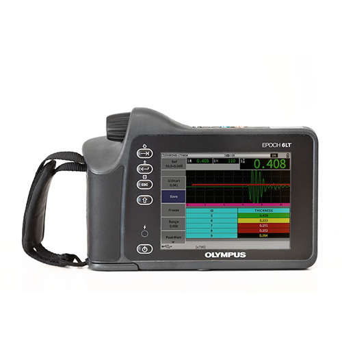
Used Olympus EPOCH 6LT Portable Flaw Detector
Olympus EPOCH 6LT portable flaw detector combines the functionality of a powerful ultrasonic flaw detection device with a form factor designed to thrive in rope access and high portability applications.
Olympus EPOCH 6LT This flaw detector is a rugged instrument that delivers user comfort and more uptime. The unit weighs just 1.95 pounds (890 g) with a grip-oriented weight distribution for one-handed operation with minimal wrist fatigue, and rotary knob and simple button design make it easy to use, even when wearing gloves.
The EPOCH 6LT flaw detector’s workflow is simple and straightforward. Despite the instrument’s small size, it has the features and functions to meet the requirements of nearly any conventional ultrasonic inspection application.
Based on the same digital architecture as the EPOCH 650 flaw detector, the EPOCH 6LT flaw detector provides flexible, powerful pulsing and receiving features to accommodate the needs of most flaw detection inspections.
General
User Interface Languages
English, Spanish, French, German, Japanese, Chinese, Portuguese, Russian, Italian
Transducer Connections LEMO 00
Data Storage 100,000 IDs onboard
Battery Type and Life Single lithium-ion rechargeable standard; 6 h life
Power Requirements AC Mains: 100 VAC to 120 VAC, 200 VAC to 240 VAC, 50 Hz to 60 Hz
Display Type Full VGA (640 × 480 pixels) transflective color LCD, 60 Hz update rate
Display Dimensions (W × H, Diag.) 117 mm × 89 mm, 146 mm (4.62 in. × 3.49 in., 5.76 in.)
Overall Dimensions (W × H × D) 209 mm x 128 mm x 36 mm, 58 mm at hand grip (8.2 in. x 5 in. x 1.4 in., 2.3 in. at hand grip)
Weight 890 g (1.95 lb), including lithium-ion battery
Instrument Inputs/Outputs
USB Ports (1) USB 1.1 Full Speed Host (Type A)
(1) USB 2.0 Full Speed Client (Type Mini B)
Video Output 1 digital video output
Environmental Ratings
IP Rating Ingress Protection (IP) engineered to IP67 (dust tight and water submersion) and IP65 (dust tight and water jets) per IEC 60529-2004 (Degrees of Protection provided by enclosures—IP Code). The product rating is confirmed by means of Olympus’ internal design verification test process.
Explosive Atmosphere MIL-STD-810F, Method 511.4, Procedure 1.
Shock Tested MIL-STD-810F, Method 516.5, Procedure I, 6 cycles each axis, 15 g, 11 ms half sine.
Vibration Tested MIL-STD-810F, Method 514.5, Procedure I, Annex C, Figure 6, general exposure: 1 hour each axis.
Operating Temperature -10 °C to 50 °C (14 °F to 122 °F)
Battery Storage Temperature 0 °C to 50 °C (32 °F to 122 °F)
Pulser
Pulser Turnable square wave
PRF 10 Hz to 2000 Hz in 10 Hz increments
Energy Settings 100 V, 200 V, 300 V, or 400 V
Pulse Width Adjustable from 25 nsec to 5,000 nsec (0.1 MHz) with PerfectSquare™ technology
Damping 50, 400 Ω
Receiver
Maximum Input Signal 20 Vp
Receiver Input Impedance 400 Ω ± 5%
Receiver Bandwidth DC to 26.5 MHz at -3 dB (standard version)
0.2 to 26.5 MHz at -3 dB (EN12668 compliant version)
Digital Filter Settings 8 digital filter sets (standard version)
7 digital filter sets (EN12668 compliant version)
Rectification Full-Wave, Positive Half-Wave, Negative Half-Wave, RF
System Linearity Horizontal: ± 0.5% FSW
Resolution 0.25% FSH, Amplifier Accuracy /- 1dB
Reject 0 to 85% FSH in 1% increment positions
Amplitude Measurement 1.25% to 110% full screen height
Measurement Rate Equivalent to PRF in all modes (single shot)
Calibration
Automated Calibration Velocity, zero offset
Straight beam (first back wall or echo-to-echo)
Angle beam (sound path or depth)
Test Modes Pulse Echo, Dual, or Through Transmission
Units Millimeters, inches, or microseconds
Range 4.31 mm to 6,700 mm at 5,900 m/s (0.2320 in./μs)
Velocity 635 m/s to 15240 m/s (0.0250 in./μs to 0.6000 in./μs)
Zero Offset 0 to 750 μs
Display Delay -10 microseconds to 2203 microseconds
Refracted Angle 0° to 85° in 0.1° increments, then jump to 90°
Gates
Measurement Gates 2 fully independent flaw gates
Gate Start Variable over entire displayed range
Gate Width Variable over entire displayed range
Gate Height Variable from 2 to 95% full screen height in 1% increments
Alarms Positive and negative threshold/curve, minimum depth (gate 1 and gate 2)
Measurements
Measurement Display Locations 5 locations available (manual or auto selection)
GATE (1, 2) Thickness, sound path, projection, depth, amplitude, time-of-flight, min./max. depth, min./max. amplitude, sizing measurements based on mode
Measurement Display Locations User selects up to four measurements from either gate to display on the live screen.
Echo-to-echo Standard gate 2 – gate 1
DAC/TCG Standard, up to 50 points, 110 dB dynamic TCG range
Special DAC Modes Custom DAC (up to 6 curves), 20–80% view
Curved Surface Correction Standard OD or bar correction for angle beam measurements.
