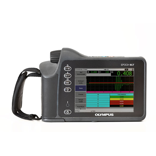
New Olympus EPOCH 6LT Portable Flaw Detector
General
| User Interface Languages | English, Spanish, French, German, Japanese, Chinese, Portuguese, Russian, Italian |
|---|---|
| Transducer Connections | LEMO 00 |
| Data Storage | 100,000 IDs onboard |
| Battery Type and Life | Single lithium-ion rechargeable standard; 6 h life |
| Power Requirements | AC Mains: 100 VAC to 120 VAC, 200 VAC to 240 VAC, 50 Hz to 60 Hz |
| Display Type | Full VGA (640 × 480 pixels) transflective color LCD, 60 Hz update rate |
| Display Dimensions (W × H, Diag.) | 117 mm × 89 mm, 146 mm (4.62 in. × 3.49 in., 5.76 in.) |
| Overall Dimensions (W × H × D) | 209 mm x 128 mm x 36 mm, 58 mm at hand grip (8.2 in. x 5 in. x 1.4 in., 2.3 in. at hand grip) |
| Weight | 890 g (1.95 lb), including lithium-ion battery |
Instrument Inputs/Outputs
| USB Ports | (1) USB 1.1 Full Speed Host (Type A) (1) USB 2.0 Full Speed Client (Type Mini B) |
|---|---|
| Video Output | 1 digital video output |
Environmental Ratings
| IP Rating | Ingress Protection (IP) engineered to IP67 (dust tight and water submersion) and IP65 (dust tight and water jets) per IEC 60529-2004 (Degrees of Protection provided by enclosures—IP Code). The product rating is confirmed by means of Olympus’ internal design verification test process. |
|---|---|
| Explosive Atmosphere | MIL-STD-810F, Method 511.4, Procedure 1. |
| Shock Tested | MIL-STD-810F, Method 516.5, Procedure I, 6 cycles each axis, 15 g, 11 ms half sine. |
| Vibration Tested | MIL-STD-810F, Method 514.5, Procedure I, Annex C, Figure 6, general exposure: 1 hour each axis. |
| Operating Temperature | -10 °C to 50 °C (14 °F to 122 °F) |
| Battery Storage Temperature | 0 °C to 50 °C (32 °F to 122 °F) |
Pulser
| Pulser | Turnable square wave |
|---|---|
| PRF | 10 Hz to 2000 Hz in 10 Hz increments |
| Energy Settings | 100 V, 200 V, 300 V, or 400 V |
| Pulse Width | Adjustable from 25 nsec to 5,000 nsec (0.1 MHz) with PerfectSquare™ technology |
| Damping | 50, 400 Ω |
Receiver
| Maximum Input Signal | 20 Vp |
|---|---|
| Receiver Input Impedance | 400 Ω ± 5% |
| Receiver Bandwidth | DC to 26.5 MHz at -3 dB (standard version) 0.2 to 26.5 MHz at -3 dB (ISO 22232-1:2020 compliant version) |
| Digital Filter Settings | 8 digital filter sets (standard version) 7 digital filter sets (ISO 22232-1:2020 compliant version) |
| Rectification | Full-Wave, Positive Half-Wave, Negative Half-Wave, RF |
| System Linearity | Horizontal: ± 0.5% FSW |
| Resolution | 0.25% FSH, Amplifier Accuracy /- 1dB |
| Reject | 0 to 85% FSH in 1% increment positions |
| Amplitude Measurement | 1.25% to 110% full screen height |
| Measurement Rate | Equivalent to PRF in all modes (single shot) |
Calibration
| Automated Calibration | Velocity, zero offset Straight beam (first back wall or echo-to-echo) Angle beam (sound path or depth) |
|---|---|
| Test Modes | Pulse Echo, Dual, or Through Transmission |
| Units | Millimeters, inches, or microseconds |
| Range | 4.31 mm to 6,700 mm at 5,900 m/s (0.2320 in./μs) |
| Velocity | 635 m/s to 15240 m/s (0.0250 in./μs to 0.6000 in./μs) |
| Zero Offset | 0 to 750 μs |
| Display Delay | -10 microseconds to 2203 microseconds |
| Refracted Angle | 0° to 85° in 0.1° increments, then jump to 90° |
Gates
| Measurement Gates | 2 fully independent flaw gates |
|---|---|
| Gate Start | Variable over entire displayed range |
| Gate Width | Variable over entire displayed range |
| Gate Height | Variable from 2 to 95% full screen height in 1% increments |
| Alarms | Positive and negative threshold/curve, minimum depth (gate 1 and gate 2) |
Measurements
| Measurement Display Locations | 5 locations available (manual or auto selection) |
|---|---|
| GATE (1, 2) | Thickness, sound path, projection, depth, amplitude, time-of-flight, min./max. depth, min./max. amplitude, sizing measurements based on mode |
| Measurement Display Locations | User selects up to four measurements from either gate to display on the live screen. |
| Echo-to-echo | Standard gate 2 – gate 1 |
| DAC/TCG | Standard, up to 50 points, 110 dB dynamic TCG range |
| Special DAC Modes | Custom DAC (up to 6 curves), 20–80% view |
| Curved Surface Correction | Standard OD or bar correction for angle beam measurements |